Calibrations
Build plate
Calibrating the build plate is one of the mandatory calibrations to perform
Initially, it might look like an impossible task to complete: you'll feel daunted and frustrated when you have to repeat the same procedure from scratch more than once, but the benefits you'll get from having a perfectly calibrated build plate are going to be priceless
Furthermore, it is a lenghty operation, but you're likely to do it once a year or so, and the more you do it, the easier it will be
- Thighten completely the four springs under the bed
- Adjust the Z endstop screw, until you get 2mm between the tip of the nozzle and the plate when homing
you can use one of the hex keys provided with the printer as reference, the second smallest one
- Initiate the bed levelling procedure via the printer GUI (graphical user interface)
- Start turning the spring handles clockwise, using the provided sheet or, alternatively, an A4 sheet (which is usually 0.1mm thick) to ensure there is a little friction between the nozzle and the bed. Repeat the bed levelling procedure multiple times, until you get the same friction for all the four (or five, if you activated the central one) calibration points
Tips for a good calibration
- Before starting levelling the bed, heat it up to the temperature you usually use to print (most common is 60 celsius degrees) and keep it hot until you're done calibrating: this is due to the thermal expansion of the plate support
- Repeat calibration multiple times
- Home on Z every time you move to a different calibration point, then home all the axes between each round of bed levelling
- Clean the bed with isopropyl alcohol (99% pure)
Test bed levelling
When you're sure the bed is calibrated, in order to test levelling, you can print a calibration file, which is going to give you visual feedback
This file should be printed very slowly, about 20mm/s, to be able to adjust any misalignement by just rotating the handles below the bed
Once completed the test print, or even while printing, it is possible to evaluate levelling by comparing your results with the table below:
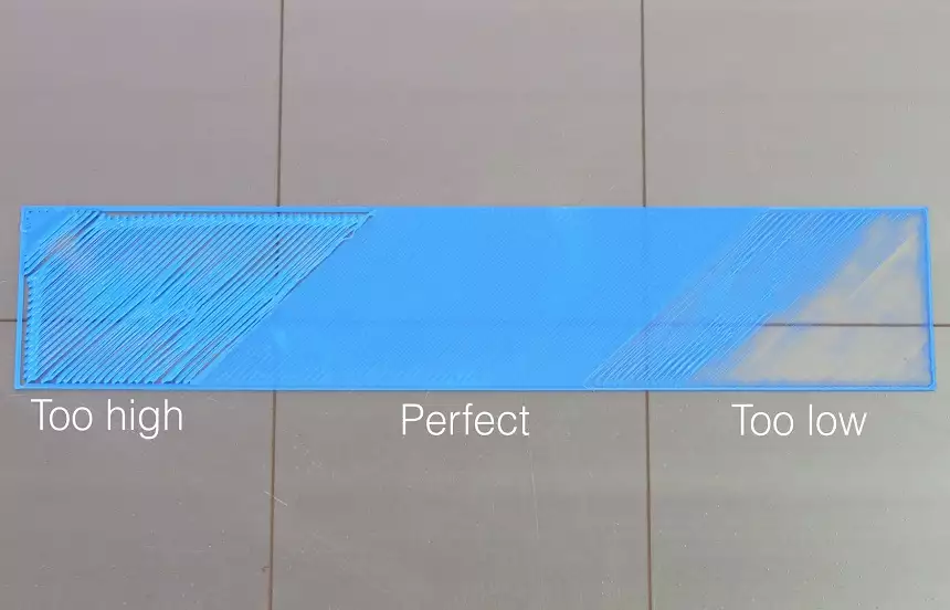
First layer outcomes examples- Credits 43dprint.org
PID Calibration
PID calibration MUST always be supervised and monitored via software, like Repetier Host: the hotend temperature could raise too much, if it goes beyond 15% of the expected temperature, SWITCH OFF IMMEDIATELY THE PRINTER!!!
PID is a control algorithm to control temperatures of nozzle and heat bed. If you are experiencing temperature fluctuations, you might have to calibrate the PID
How do I do it???
First of all, download a software that can send gcode to the printer
Our favourite is Repetier Host
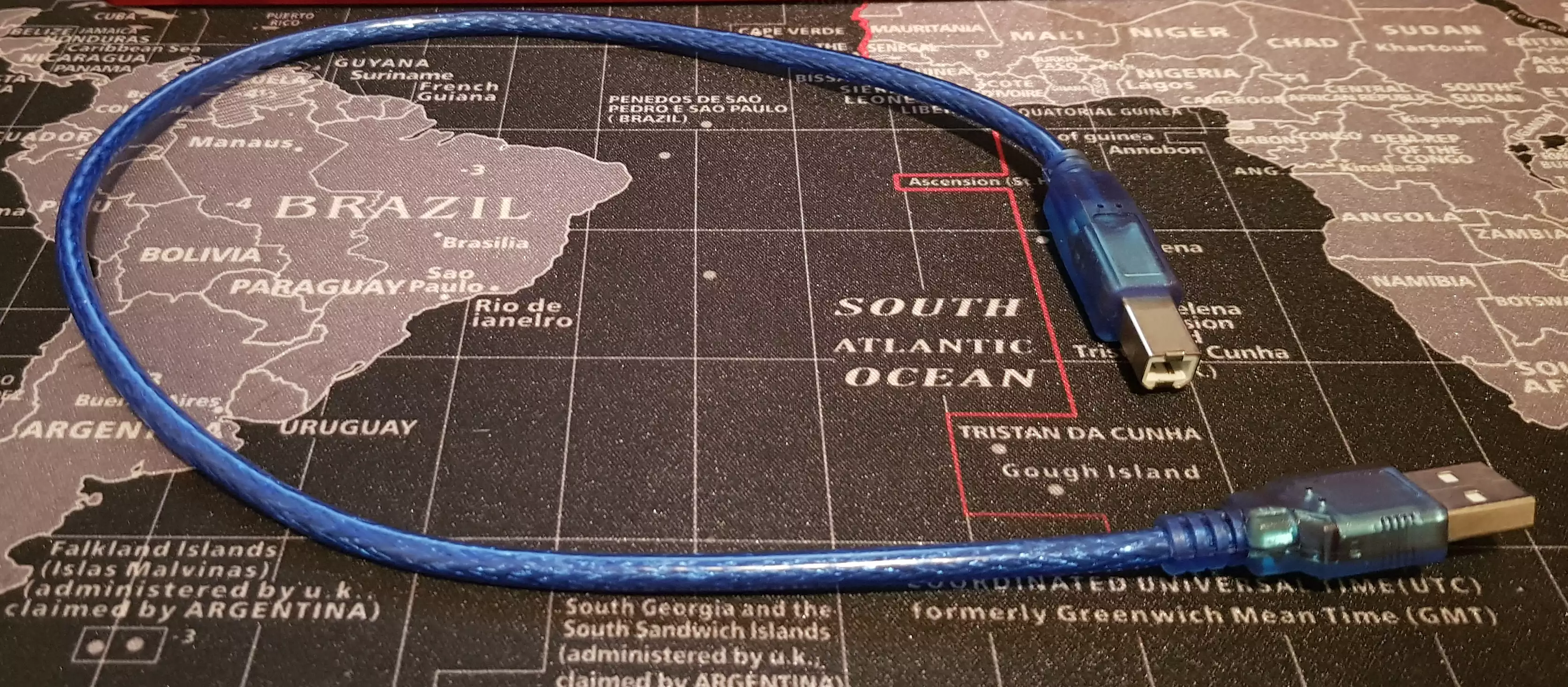
Before launching RH, connect the printer to the USB port of your computer via the cable provided with the printer (the blue one, USB A on one side, USB B on the other side, like the one in the picture below)
Make sure printer has been recognised by the system
For *nix systems, like Ubuntu and macOS, there's nothing to do: only connect the cable
For Windows, sometimes it might be necessary to install the driver CH34X
After installing the driver, ensure the printer is connected:
- Open Control Panel
- Scroll down the list of devices
- Look for the printer (should be installed on COM port)
In both cases, right now you can launch Repetier Host (from now on , RH)
RH can't automagically find the printer, you need to select the right COM port
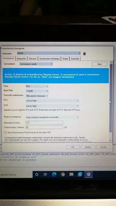
If the COM port has been correctly selected, the "connect" button will change colour. In this case, click on it
After a while (takes a bit for repetier to open the communication...), you should be able to see a couple of logging outputs in the bottom part of RH
If you don't like how verbose the M105 command is, which is a simple ping for the printer, you can disable it by navigating to Preferences and select Remove temperature request from log
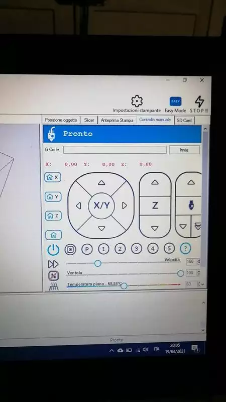
To send gcode commands to the printer, go to the tab Manual Control
Hotend PID Calibration
Before starting calibration, the nozzle needs to be heated up, taking it to the temperature you usually use (in most cases, it is about 200/210 celsius degrees) and the fan needs to be turned on
To heat up the nozzle, use the slider in the GUI to set it to the desired temperature, then wait until it's fully heated
To turn on the fan, click on the fan icon in the GUI
Alternatively, the gcode to turn on the fan is:
M106 S255
::
Once the desired temperature has been reached, in the top right corner, in the Manage section, you'll find a field to send the gcode
The first command to send is this:
M303 E0 S210 C8;
M303 is the gcode to start PID calibration
E0 is the target hotend, the one to calibrate (All Ghosts have only one, by default)
S210 is the chosen temperature. For instance, if you usually print at 200 celsius degrees, use S200
C8 is the number of cycles to repeat the calibration process. 8 is the recommended value for Marlin based firmware :::
After issuing this command, the hotend PID calibration will start
It will take a while, but then the output will stop running, which means calibration is completed
Now look at the log: you'll see some messages similar to the ones below at the bottom of the log output:
20: 44: 36.845: PID Autotune finished! Put the last Kp, Ki and Kd constants from below into Configuration.h
20: 44: 36.849: #define DEFAULT_Kp XX.XX
20: 44: 36.849: #define DEFAULT_Ki X.XX
20: 44: 36.853: #define DEFAULT_Kd XX. XX
Where you see the XX, you'll find the three new values to update after calibration
In order to update these values, there are two options:
Via robin_nano35_cfg.txt file
Take the values you found, then insert them in the robin_nano35_cfg.txt
Look for the lines below in the file (the numbers below are only for demonstration purpose)
PIDTEMPE 1 # Mode 1: PID; 0: bang-bang
DEFAULT_Kp 11.14 # P value
DEFAULT_Ki 0.72 # I value
DEFAULT_Kd 43.09 # D value
The first line changes the temperature regulation system from bang bang to PID (which is what we want)
In the second, third and fourth line, insert the values you just found using RH
As usual, upload the robin_nano35_cfg.txt file on the SD, then insert the SD in the printer, turn it off and on again
Via Repetier Host
In the Manual Control tab, send the following gcode, replacing the values with the ones you just found (the numbers below are only for demonstration purpose)
M301 P24.36 I1.39 D106.76
This command will change the values of the PID, so the printer is already updated. This values, though, have not been saved in the EEPROM (the persistent memory of the printer), which means that, once you turn off the printer, the PID values will go back to your previous ones
In order to make things permanent, use the following command:
M500
After launching it, to test values have been saved correctly, use the following command:
M503
In the terminal output window you should be able to see the actual PID values, which should be exactly the same as the ones you've just sent
Et voila', the hotend PID is calibrated!
Heatbed PID calibration
Calibrating the heatbed PID is very similar, although there is another change to make in the config file
PID calibration for the heatbed is disabled by default, so in the robin_nano3_cfg.txt file you must amend the following parameter:
PIDTEMPBED 0
Set it to
PIDTEMPBED 1
Once this value has been updated in the firmware, i.e. you've inserted again the SD card and applied all the changes, you can use the following gcode to start the PID calibration
M303 E-1 S70 C8;
S70 is the chosen temperature. If you usually print with the heatbed at 60 degrees celsius, replace S70 with S60
After completing calibration, the values will be displayed in the terminal output, just like the hotend
Same as the hotend, to update PID values for the heatbed there are two options:
Via robin_nano35_cfg.txt
Take the values from the output and insert them in the robin_nano35_cfg.txt file in the following lines (the values below are only for demonstration purpose):
>DEFAULT_bedKp          52.63
>DEFAULT_bedKi          9.75
>DEFAULT_bedKd          71.01
In the first, second and third line, insert the values you've just found with RH
As usual, upload the robin_nano35_cfg.txt file on the SD, insert the SD in the printer, turn it off and on again
Via Repetier Host
In the Manual Control tab, send the following gcode, replacing the values with the ones you just found (the numbers below are only for demonstration purpose)
M304 P824.78 I154.89 D1097.99
This command will change the values of the PID, so the printer is already updated. This values, though, have not been saved in the EEPROM (the persistent memory of the printer), which means that, once you turn off the printer, the PID values will go back to your previous ones
In order to make things permanent, use the following command:
M500
After launching it, to test values have been saved correctly, use the following command:
M503
In the terminal output window you should be able to see the actual PID values, which should be exactly the same as the ones you've just sent
Et voila', the heat bed PID is calibrated!
Steps
Sometimes, you might have noticed some imperfections on the walls of your prints, like blobs, zits, or maybe just some inconsistencies in how your filament is layed out
This problem could be due to the extruder, the mechanism which is bringing the filament from the spool to the hotend
The extruder engine is placed internally on the back panel of the printer, kept in place by the extruder gear, which is still placed on the back panel of the printer, but externally
The engine (Nema17) has, by default, 200 steps per rotation: this means that, in order to complete a rotation, it takes 200 steps. This mean one step corresponds to 1.8 degrees
The step per millimeter of an engine, though, are the steps the engine needs to cover the distance of 1 millimeter
The default value of the steps per millimeter of the extruder on the Ghost is 400, which means that, in order to move by 1 mm, the engine should fully rotate twice
Unfortunately, not all components are the same, therefore, in order to stabilize the flow or the axis movements, it is necessary to calibrate these values
Extruder
In this case, it is necessary to use Repetier Host (RH). We explained how to first connect in the First Steps section
First of all, connect the printer via the USB cable, open RH, make sure printer is connected, then move to the Manual Control tab to send gcode commands
Now that everything is ready on the software side, let's go and see what to do with the hardware
The first step to do is to unload the filament from the nozzle, if present. Do so using the control panel on the printer itself. Actually, remove the filament altogether
Once you've removed the filament, extract the teflon tube from the extruder: first remove the zip tie (if present), then press the release cap and finally extract the teflon tube
Now insert the filament again in the extruder by hand, but stop when it just comes out of the extruder hole. Using wire cutters, remove the excess filament, until it is levelled with the top part of the extruder
Now, send the following gcode commands to RH:
 M302 P1; Disable extruder thermal protection
 G92 E0; Set the origin of the extruder to the current position
 G1 E280 F800; Extrude 280mm of filament
The filament will then come out of the extruder and its length must be measured with a ruler, or whatever tool you prefer to use
To calculate the real steps, use the formula:
400 * (280/x) ==> x = lenght of the extruded piece of filament
400 is the default number of steps
If, for instance, we measured 265, the formula above would be:
400 * (280/265)
Once you've calculated the new value, you need to set it in the firmware
To update via robin_nano file, look for
DEFAULT_E0_STEPS_PER_UNIT
Now replace the default value with the one you got from the formula, then update the firmware with the new value
To update steps/mm via gcode, you can use the following gcode command:
M92 EXX.X
Where XX.X is the value of the step/mm you calculated
To store this value in memory, complete this procedure by sending the following gcode:
M500
We strongly suggest to make some test prints BEFORE and AFTER calibration, to compare results
Recommended:
Axes
Printing interlocking items is one of the most difficult things in 3d printing, because of the material expansion and/or inaccuracy of the original model
In order to get prints which have an error margin of the hundredth of a millimeter, the axis too need some calibration, which can be done using a simple calibration cube and a caliper with the resolution of the hundredth of a millimeter
Before we get started, let's download a test file from here:
Alternatively, you can launch your favorite CAD tool and make it yourself
Once you've printed the cube, let's take some notes about the steps of each axis
The default ones for the Flyingbear Ghost are reported below
| X | Y | Z |
|---|---|---|
| 80 | 80 | 400 |
Alternatively, you can send the M503 gcode command (for instance, via Repetier Host)
From the output, you can extract the following line:
M92 X__ Y__ Z___ E__
Where the values represent, respectively, the steps of the X, Y, Z axis and the extruder's
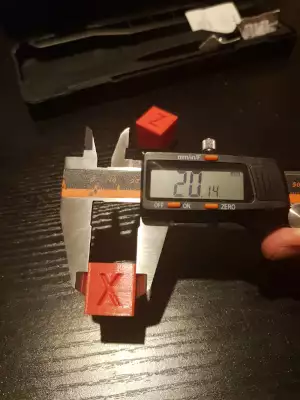
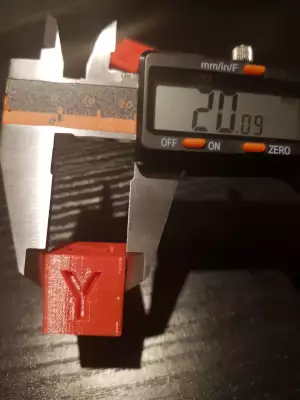
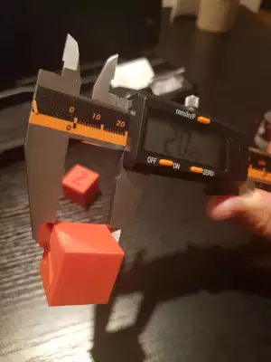
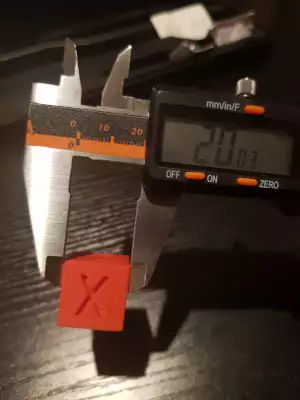
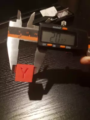
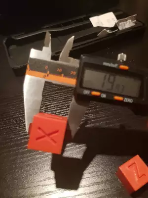
Now let's go and measure the cube
The cube in the link is really useful to better understand what axis you are measuring If the caliper points towards the side with the X, then you're measuring the X axis, and so on
Now let's calculate the proportion, which can be formulated like this:
If I get XXmm with XX steps, how many steps do I need to get my expected value???
current_steps : actual_measure = optimal_steps : expected_measure
which can be translated to the following formula:
optimal_steps = (current_steps * expected_measure)/actual_measure
Looking at the picture, we'll have:
(80 * 20mm) / 20.14mm = 79.4

(80 * 20mm) / 20.09mm = 79.6

(400 * 20mm) / 20.26mm = 394.8
Now we can update the printer steps, as usual, via the robin nano (as previously described), or sending some gcode commands:
M92 X79.4

M92 Y79.2

M92 Z394.8
The gcode commands above must be sent one by one, not all together!
To save values on the EEPROM, send the following gcode:
M500
Now let's go and read the values of the step to ensure everything is ok by sending the gcode command M503
If everything is ok, we're ready to print the calibration cube again and measure the new values
As you can see from the images, we have:
- +0.03 on the X axis, while it was +0.14 before
- +0.02 on the Y axis, while it was +0.09 before
- -0.07 on the Z axis, while it was +0.26 before
