First Steps
Firmware
The firmware, which is the "operating system" of a 3d printer, is installed in the motherboard memory, located inside the printer base
It can be be easily updated using the SD provided with the printer, although we strongly suggest to replace it with a more performing one
The first advice we can give is to install the most up to date tested firmware, which can be downloaded from Github (you can find the link in the top right of this website or, alternatively, in the Firmware section): it usually contains multiple bugfixes and will prevent you from having inconsistencies with the guides in the wiki (which are usually targetting the latest tested firmware for any given motherboard/drivers combination)
Alternatively, if you feel brave, you can find the latest firmwares released by Flyingbear here
The first thing to do is to backup the content of the SD (this is not mandatory, if you don't care about the original content of the SD, which should contain only the config file for your printer and the stl and gcode files for the nut and screw, the test print provided by Flyingbear)
Once you've backed up the content of the SD, you can:
- Download the firmware
- Extract it in a folder (we strongly suggest to keep it in a safe location, as a backup)
- Format the SD card in FAT32
- Copy the content of the folder (including the sub folders!!!) in the SD card
- Safely remove the SD from your computer
- Inser the SD card into the printer (be careful: the SD card should be inserted upside down, with the metal pins facing upwards!!!)
- Switch off the printer (only if it's already on)
- Turn the printer on
Once you've turned the printer on, the Flyingbear logo will appear, then a progress bar, showing you the progess status of the installation
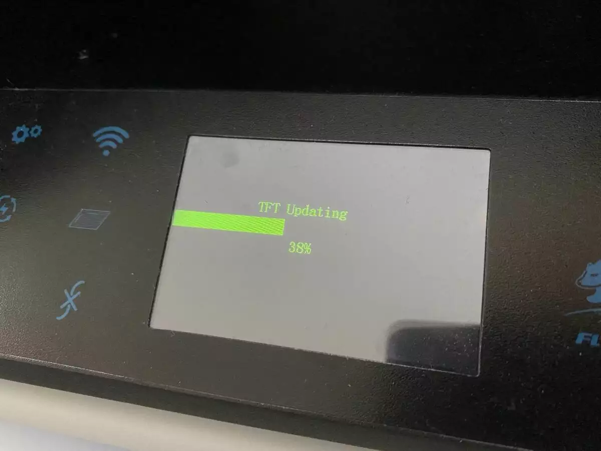
Once installation is completed, you should see the main menu appearing on the screen
Congratulations: you're one step closer to your first 3d print with the Flyingbear Ghost!
Now, don't get tempted to start playing around with the menu, but follow the next steps:
- Extract the SD card from the 3d printer
- Insert it in your computer
- Download the robin_nano35_cfg.cur file from the SD card to a safe location in your computer
- Open it with Notepad (or your favourite text editor, but NEVER EVER with word, or any other word processing application!!!)
- Save it as robin_nano35_cfg.txt (if you want to rename it from the File Manager, you can select the file and hit F2 for Windows and Ubuntu or Enter for Mac)
This file contains the main parameters of your printer. Changing a value in this file will let you update the related parameter in the firmware
Now let's go and see what we have to change
Open the file robin_nano35_cfg.txt you saved previously, then look for the following lines and amend the corresponding value
Always remember to leave at least one space between the parameter, which is in capital letters, and the corresponding value
Multiple spaces don't matter
Language
cfg_language_type 7 # Language selection 2 - English 3 - Russian 7 - Italiano
Safety
HEATER_0_MINTEMP 5 # It is recommended to set exactly 5 (not -5) to avoid overheating if the sensor
HEATER_1_MINTEMP 5 # It is recommended to set exactly 5 (not -5 ) in order to avoid overheating in the event of a sensor breakdown
THERMAL_PROTECTION_PERIOD 30 # Polling time for thermal protection, seconds
THERMAL_PROTECTION_HYSTERESIS 10 # Change in degrees C
WATCH_TEMP_PERIOD 30 # Polling time for thermal protection, seconds
WATCH_TEMP_INCREASE     2
THERMAL_PROTECTION_BED_PERIOD 30 # Poll time for thermal protection, seconds
THERMAL_PROTECTION_BED_HYSTERESIS 3 # Change in degrees C
WATCH_BED_TEMP_PERIOD 60 # Poll time for thermal protection, seconds
WATCH_BED_TEMP_INCREASE 2 # Change
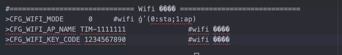
Wifi
CFG_WIFI_AP_NAME # name of WiFi, write before #
CFG_WIFI_KEY_CODE # password WiFi, write before #
Just insert, like in the picture below, the name of your Wi Fi network and your Wi Fi password
Fifth calibration point
It is possible to add a fifth calibration point to the interface (by default, they are four, located in the corners), to be able to level the bed in the middle too, other than in the corners
The first four points are ok, coordinates are correct, but the fifth point should be central
Amend the coordinates to get to the center of the bed, you can check this by manually moving the head to middle of the hotbed
 cfg_point_number 5
 cfg_point1:30,30
 cfg_point2:235,30
 cfg_point3:235,190
 cfg_point4:30,190
 cfg_point5:125,105
Procedure to update is always the same as mentioned before
Final remarks
Once you've completed the previous steps, your best move will always be making a copy of the robin_nano_cfg.txt and the delete the content of the SD
Right now, your printer is finally ready to print! Exciting!!!
To increase print quality, though, there are some further calibrations to perform
In the next page, you'll find all the necessary calibrations to get the most out of your 3d printer
